Gas Chromatography
Gas chromatography (GC) describes a separation process in which volatile organic compounds of a sample partition between a flowing mobile phase (i.e., carrier gas) and a stationary phase (i.e., separation column). The GC method used in this study measured for CO, CO2, C1 to C8 hydrocarbons and C1 to C11 oxygenated compounds. A GC unit includes a flowing mobile phase (carrier gas), a stationary phase (separation column), an injection port, an oven, and a detector. The carrier gas carries the sample through a separation column where the compounds in the sample gas partition into the separation column, based on their solubilities at the given temperature. Since partitioning behaviour is strongly dependent on temperature, the separation column is placed in a temperature-controlled oven. Compounds are separated with a range of boiling points by starting at low temperatures and then increasing the temperature until the high boiling point compounds are eluted. The injection port is maintained at a temperature higher than the boiling point of the least volatile compound in the gas mixture. The retention time is the amount of time a compound spends in the separation column. As each compound of the separated sample gas passes through the detector, a quantitative response in the form of a peak is generated by the detector signal and a collection of these peaks make up a chromatogram. The detector signal is proportional to the quantity of each analyte. Two types of detectors that were utilized in this study – flame ionization detector (FID) and thermal conductivity detector (TCD). The peak retention time is used to identify each compound and the
area under the peak is used to quantify the amount of each compound. A sharp peak indicates good separation. The retention times and peaks of each compound were determined using calibration gases of known concentrations.
Flame Ionization Detector
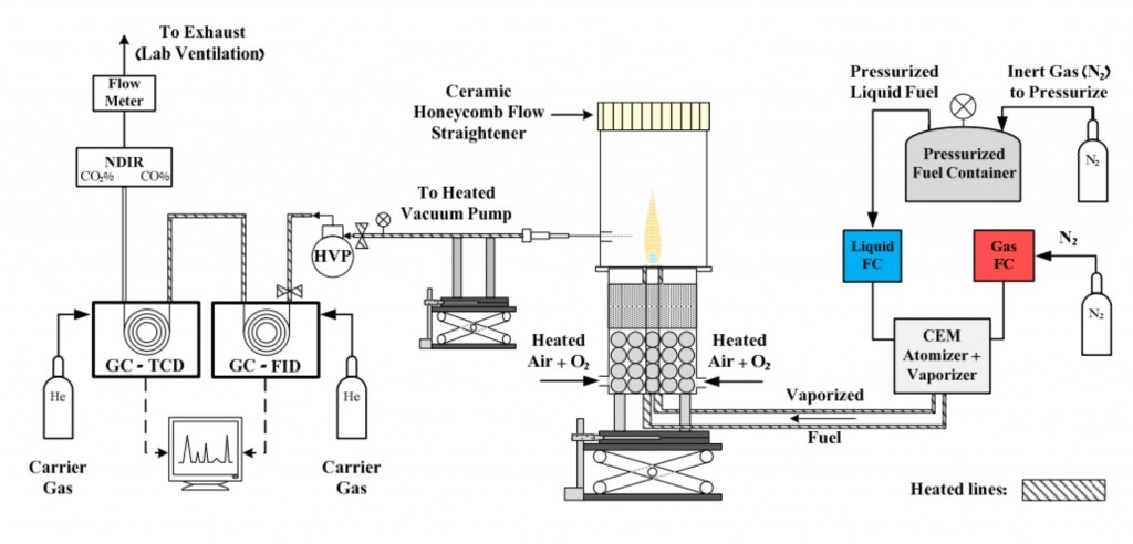
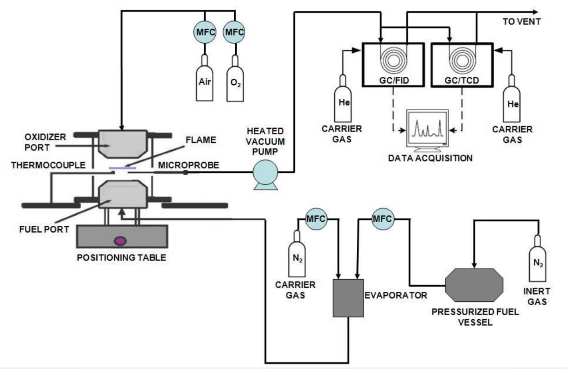
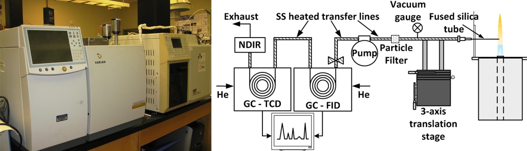
The instrument used in this study is a Varian 3800 GC with electronic flow controllers, a 1079 injector, a methanizer, and two flame ionization detectors (FID). The FID consists of a hydrogen/air flame and a collector plate. As gas components are eluted from the separation column, the flame burns the organic molecules to produce ions. These ions are attracted to the collector plate, which generates a current. This measured current corresponds to the quantity of ions present and is proportional to the quantity of the component in the detector. Since the hydrogen/air flame ionizes the organic molecules, this detection method is destructive. The GC/FID was remotely controlled by the Galaxie Chromatography Data System Ver. 1.9 software. The injection system is comprised of a gas sample loop, a gas sampling valve (GSV), and an injector. The heated vacuum pump delivers the gas sample from the flame and fills the 0.25 mL GC sampling loop. The 10 port rotary GSV directs the gas sample and carrier gases into the injector. In the GSV’s fill position, the gas sample flow through the sample loop and the carrier gas flow to the injector and separation column. Once the GSV is switched to the load position, the gas sample in the sample loop gets carried with the carrier gas flow through the injector and into the separation column.
The injector is a Varian 1079 universal capillary injector equipped with a splitless insert. A splitless insert allows for the entire gas sample to be loaded into the separation column; thus, allowing for trace compounds to be detected. A split insert can be used to load a portion of the gas sample into the separation column.
Once the gas sample passes through the injector, it moves into a 0.5 m fused-silica retention gap before passing through a y-splitter where it is split to two columns for separation. C1 to C8 hydrocarbons are separated on a non-polar phase HP-Al/S PLOT capillary column8 and are detected on the front FID. Oxygenated species, such as aldehydes, ketones, and alcohols, are separated on a polar phase Poraplot U-capillary column9, and are passed through a methanizer before detection on the FID. The FID provides a response proportional to the analyte’s concentration and number of carbon atoms. For example, the detector signal for 1 mole of ethane (C2H6) would be about double the magnitude for 1 mole of methane (CH4), and 1 mole of propane (C3H8) would be about triple that of 1 mole of CH4. Molar response factors have been examined by Schofield for a number of hydrocarbon and oxygenated species [57].
Oxygenated species have lower responses because the FID flame cannot break down carbon-oxygen bonds. Thus, species like formaldehyde and carbon monoxide register zero response on the FID, while higher oxygenated hydrocarbons provide weaker responses than their non-oxygenated counterparts. To improve the FID’s response to oxygenated compounds, the separated sample gas was passed through a methanizer before being burned in the FID. The methanizer is a 1/16 inch stainless steel tube packed with a powered nickel catalyst. The methanizer is heated to 380 °C and requires a constant flow of hydrogen gas. As the gas sample flows through the methanizer, the nickel catalyst breaks the carbon-oxygen bonds and then saturates them with hydrogen. Thus, all carbon-oxygen bonds are converted to carbon-hydrogen bonds. For example, formaldehyde appears as methane and acetaldehyde appears as ethane on the FID. In this study, the C-O to C-H conversion was assumed to be 100% efficient.
Thermal Conductivity Detector
The thermal conductivity detector (TCD) measures the changes in thermal conductivity in a reference carrier gas caused by the eluted components from the gas sample. Thermal conductivity describes the rate at which a material can transfer heat and is strongly temperature-dependent. Measurement with a TCD is based on monitoring changes in the electrical resistance of a heated filament caused by variations in its temperature as the eluted components passes through the measuring cell. When a component appears in the carrier gas, the thermal conductivity of the carrier gas is altered, resulting in a change in temperature and resistance of the heated filament. These changes in temperature and resistance produce a corresponding voltage signal. This type of detector is generally sensitive to all substances except the carrier gas. The TCD has the advantage of not destroying the analyte, which happens in a FID. Although a TCD is less sensitive than a FID, a TCD has the ability to detect pure substances such as O2, N2, CO, and CO2. The GC/TCD was remotely controlled by the Galaxie Chromatography Data System Ver. 1.9 software.
The instrument used in this part of the study was a Varian 450-GC. Similar to the system found on the GC/FID, this Varian 450-GC consists of a gas sample loop, two GSVs. The gas sample is introduced to the system with an Electronic Flow Control (EFC) pneumatic system for constant pressure control and constant total flow control. The first GSV loads the gas sample into the 1 mL sample loop and then injects the gas sample into the stream of carrier gas, where the mixture is delivered to the separation columns. The two columns in series are used for separation: a Hayesep Q packed column and a Molecular sieve packed column11. The fraction containing oxygen (O2), nitrogen (N2), carbon monoxide (CO) and methane (CH4) is flushed onto the Molecular Sieve column and are parked there. The remaining fraction, mainly carbon dioxide (CO2), C2 isomers, and water (H2O) bypass the Molecular Sieve column and are eluted to the TCD. The Molecular Sieve column is then set to flow again, allowing for the separation of O2, N2, CO, and CH4 and the detection of these species on the TCD. While the GC/TCD can quantify many species, only the concentrations of CO, CO2, and O2 were quantified in this study with this technique.
The GC/TCD is equipped with oxygen, moisture and charcoal filters to remove impurities from the carrier gas. Helium gas at an inlet pressure of 80 psig served as the carrier and make up gas. Instrument air at 60 psig was used for valve operation.
The strength of the TCD response signal depends on the concentration of the eluted components that has a different thermal conductivity than that of the carrier gas. Thus, gas components with thermal conductivities close to that of the carrier gas will elicit small responses, while those that differ more from the carrier gas will show larger responses.